
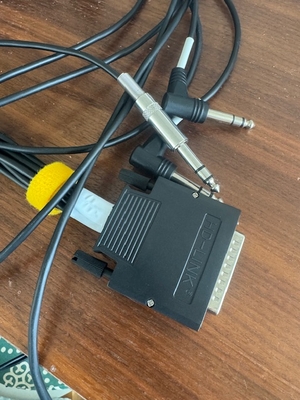
 Several years ago, I bought the Donner DED-200 drum kit as a birthday present for my son, who had dreams of becoming a drummer. As you might predict, he ended up favoring the guitar and piano, leaving the drum kit to gather dust in the corner. That’s when I decided to tackle the set and bring it back to life. Because, maybe I could be a drummer. Why not? The problem was that the ride crash cymbal pad wasn’t working.
So I rolled up my sleeves and got to work. This was the second problem. In my eagerness to fix the issue, I made an early misstep: instead of simply cutting the non-working ride crash cymbal TRS cable to check for line continuity, I ended up dismembering the entire plug including the DB-25 pin connector. This mistake set me on a path of troubleshooting that I hadn’t anticipated, and a world of pain.
I scoured the internet for 25-pin pinout diagrams to decipher how the pins were wired, hoping these diagrams would reveal which of the octopus cables belonged to each pin. Unfortunately, I came up empty-handed, as there was no information available for the Donner kit—or even for Medeli, the OEM manufacturer of the kit (or so the internet would have us believe).
With few options left, I had to learn to use my multimeter from scratch. Through many hours of painstakingly wiring and testing each connection, I eventually put together my own version of the pinout. I won’t claim it’s perfect, but if you’re stuck like I was, it might just help you out. And if anyone can point out where the crash choke is, please drop me a line—I’m still on the hunt!
I ran out of steam after getting everything else (I think) working. If you have a better idea or spot something amiss (and let’s face it, you probably do, given that I was a novice in this area), please let me know so I can correct it—and my kit!
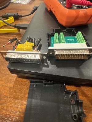
Here are a few links that were useful in my journey:
If my attempts have helped you or if you have insights to share, I’d love to hear from you!
Donner DED‑200 DB‑25 Pinout
| Pin # | Purpose | Type | Wire | Notes |
|---|---|---|---|---|
| 1 | Hi‑hat controller (Tip) | Tip | White | Sleeve to common ground |
| 2 | Hi‑hat controller (Ring) | Ring | Red | Sleeve to common ground |
| 3 | Hi‑hat pad | Tip & Ring joined | White & Red | Both wires joined on pin 3; works for single-zone hi‑hat |
| 4 | (No trigger) | — | — | Currently unused—no sensor responds |
| 5 | Snare (Tip) | Tip | White | Sleeve to common ground |
| 6 | (Unknown / Possibly ground?) | — | — | Not currently used in this wiring |
| 7 | (Earth / Common Ground?) | — | — | Ground |
| 8 | Tom #2 | Tip & Ring joined | White & Red | Sleeve to common ground |
| 9 | (Unassigned) | — | — | Not in use |
| 10 | (Unassigned) | — | — | Not in use |
| 11 | (Unassigned) | — | — | Not in use |
| 12 | Ride (Tip) | Tip | White | Sleeve to common ground |
| 13 | (Unassigned) | — | — | Not in use |
| 14 | (Unassigned) | — | — | Not in use |
| 15 | (Unassigned) | — | — | Not in use |
| 16 | Crash (Tip) | Tip | White | No choke found yet |
| 17 | (Unassigned) | — | — | Not in use |
| 18 | (Possible Ground?) | — | — | |
| 19 | Tom #1 (Tip) | Tip | White | Sleeve to common ground |
| 20 | (Likely Open) | — | — | |
| 21 | (Unassigned) | — | — | Not in use |
| 22 | Tom #3 (Tip) | Tip | White | Sleeve to common ground; single‑zone tom |
| 23 | (Unassigned) | — | — | Not in use |
| 24 | Kick (Tip) | Tip | White | Sleeve to common ground |
| 25 | (Unassigned) | — | — | Not in use |